")

Track measurement system for existing and new carrier vehicles


The Track Measurement System designed by HuDe is perfectly suitable for the integration in existing vehicle systems.
The mounting of the individual modules on the vehicle doesn’t imply a great effort and the number of cables to be laid are reduced to a minimum. The compact dimensions of the components allow their use also in case of limited space.
Due to the flexible design, the system can be expanded by further components at any time.
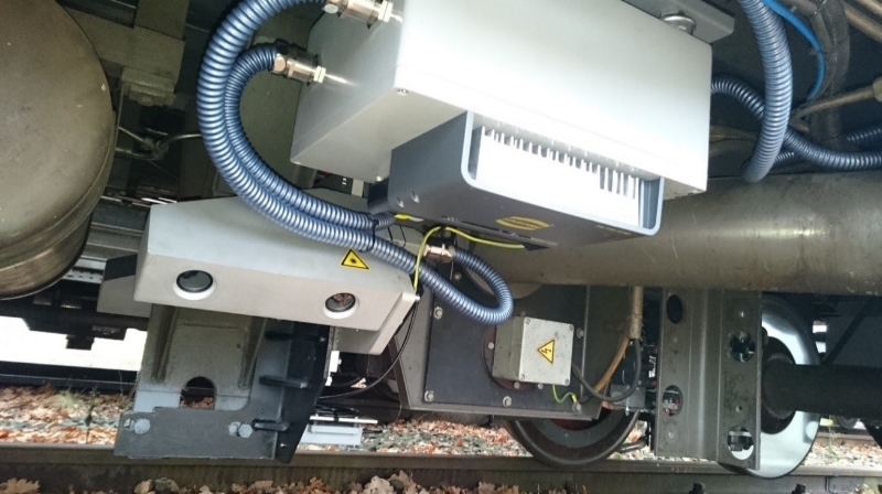
Geometry Measuring Axis
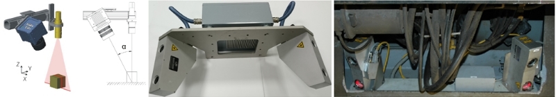
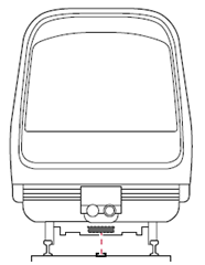
The Geometry Measuring Axis, mounted below the carrier vehicle, consists mainly of two optical sensors based on Laser-Triangulation principle, measuring the individual rails. A Laser line is projected on the rails, which is captured by an area scan camera under a defined triangulation angle. The Laser line, visible as height profile inside the camera pictures, is analysed by computer vision algorithms to measure the rails course with very high accuracy.
The geometry measuring axis were designed with 3D design software and can therewith be easily adapted to the given railway vehicle.
Inertial Measuring System Unit (IMU)
The Inertial measuring unit (IMU) consists of three accelerometers and three high precision optical fibre gyroscopes. Based on these sensors, the vehicles 3D orientation and rotation rates are calculated, representing the exact track courses Altitude, Cant, Torsion and Deviation. A special algorithm is used to compensate gyroscope drifts steadily, accrued by gyroscope data integration.
In addition to the platform temperature, the inherent drift errors, the acceleration, and the vehicle speed is taken into account for compensation. In this way, drifting and output errors are reduced to a minimum, improving the long-term stability. The IMU is an integral part of the measuring axis, making compensation of optical sensors.
It is integrated into the measuring axis, which makes the whole system compact. Therewith expensive and precision reducing corrective calculations become superfluous.
On-Line visualization of all track parameters
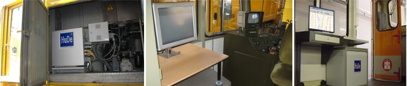
The continuously measured sensor data are acquired independently from the traveling speed by a multi- channel transient recorder system with FIFO (First In / First Out) Memory. The sampling rate for track geometry measurement is adjustable by the user between 5 and 1000 mm. The track parameters are online calculated and visualised on a graphic display. The track values are shown at an adjustable scale and can be checked by an operator online.
Comparisons with previous measurement data are available and with the Excel export function it is possible to convert the data into tabular form.
Assessment and classification of the measurement results
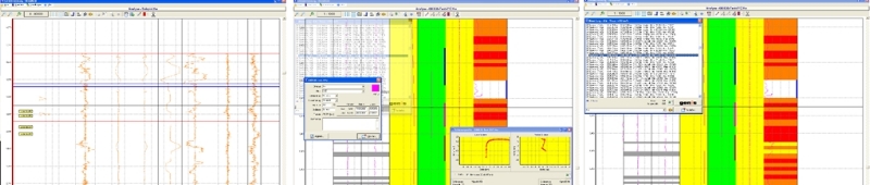
An expert system, integrated into the track measurement software, permits an analysis of the track measurement results and a classification of selectable track sections, with a multistage mark system.
The user can predefine classes according to the maximal allowed route speed and the software uses the chosen class as intervention thresholds to detect and select faulty areas on the track. After this the calculated data of the faulty areas can be transferred to maintenance railway vehicles.
|
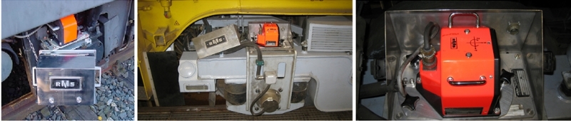
RFID SYSTEM
The HuDe- TMS will be equipped with a RFID-Reader, mounted on the main geometry measuring axis. During long-travel, this Reader recognizes RFID-Tags placed inside the track, to detect the accurate location. Furthermore it enables the TMS to perform fully automated acquisition. Therefore the RFID-Tags are used to mark the beginning and ending of a track and the TMS records measuring data accordingly. The manual parametrization of test-runs becomes obsolete. The RFID-Tags used by the HuDe-TMS are specially designed for use in harsh environments and railway applications and can be detected reliably even at high speeds. |
|
 |
GPS Track Recording
To record the tracks exact location, the system can be extended with a high precision GPS Receiver. The recorded data can be used to show the tracks on topographic maps, for example. Additionally, the GPS data is used to compensate the Inertial Measuring Unit (IMU) and vice versa. This further increases the long-term stability and accuracy of the measuring results.
Mobile Network Access
The measurement data recorded by the system, especially in fully autonomous operation (RFID-System required), can be transferred to a data-server via mobile network connection, automatically. Therewith the data is directly available in the office for detail analysis and for backup reasons.
Additionally, the mobile access is used to send information about the system status to defined recipients via E-Mail, and to connect to the system remotely in case of a failure.
The Mobile Network connection is highly secured to safely prevent from unauthorised access.
Technical Data:
|
POWER SUPPLY |
|
|
|
|
|
Supply: |
230V / 50Hz (other voltages on demand) |
|
Power consumption: |
approx. 1 kW |
|
|
|
|
ENVIRONMENT |
|
|
|
|
|
Environmental conditions: |
Temperature: -10 … +40 °C |
|
|
Relative humidity: 95 % (not condensing) |
|
|
|
|
AQUISITION |
|
|
|
|
|
Speed recording: |
2 channel system with direction control |
|
Distance recording: |
- incremental - wheel wear correction (adjustable by factors) - compensation through RFID-Position-Detection (optional)
|
|
Transient recorder: |
|
|
Dissolving: |
16 Bit |
|
Sample frequency: |
adjustable, 4 to1000 values per meter (120 Hz max.) |
|
Maximum speed: |
200 km/h |
|
Intermediate memory: |
FIFO (First In – First Out) |
|
|
|
|
ACCURACY |
|
|
||
|
|
|
|
|
|
|
Track parameter: |
Uncertainty |
Resolution |
Range |
|
|
Gauge |
+/- 1 mm |
<= 0,5 mm |
-15 mm .. +50 mm |
|
|
Altitude |
|
|
|
|
|
3 m < λ ≤ 25 m |
+/- 1 mm |
<= 0,5 mm |
+/- 50 mm |
|
|
25 m < λ ≤ 70 m |
+/- 3 mm |
<= 0,5 mm |
+/- 100 mm |
|
|
70 m < λ ≤ 150 m |
+/- 5 mm |
<= 0,5 mm |
+/- 300 mm |
|
|
Cant |
+/- 5 mm |
<= 0,5 mm |
+/- 225 mm |
|
|
Curvature |
|
|
|
|
|
3 m < λ ≤ 25 m |
+/- 1,5 mm |
<= 0,5 mm |
+/- 50 mm |
|
|
25 m < λ ≤ 70 m |
+/- 4 mm |
<= 0,5 mm |
+/- 100 mm |
|
|
Torsion |
+/- 1,5 mm/m |
<= 0,5 mm/m |
+/- 15 mm/m |
|
|
Deviation right |
+/- 3 mm |
<= 0,5 mm |
+/- 45m (curve radius) |
|
|
Deviation left |
+/- 3 mm |
<= 0,5 mm |
+/- 45m (curve radius) |
|
|
|
|
|
|
|
|
|
|
|
|
|
|
Profile Analysis right |
Analysis upon consultation |
|||
|
Profile Analysis left |
Analysis upon consultation |
|||
|
Drive Dynamics Stress |
+/- 0,01 g (resolution) |
|||
|
|
|
|||
|
According to DIN EN 13848-1:2008 |
|
|
||
|
More track parameters on demand! |
|
|
||
|
|
|
|
||
|
GPS TRACK RECORDING |
|
|
|
|
|
|
|
GPS compensated by Gyroscope at good satellite coverage. |
||
|
|
||
|
|
Typical accuracies: |
|
|
Standard |
<= 2,5m |
|
|
Corrected via SBAS |
<= 1,5m |
|
|
Corrected via DGPS |
<= 1m |
|
|
|
|
|